High Voltage Experiments
Flyback transformers are a great tool for experimenting with high voltage. These transformers were commonly used in CRT monitors/televisions and are designed to generate the high voltage necessary for the operation of the screens.
I did some experiments with high voltage when I was in college. I don't have many details left of the design, but I am including what I have below – mostly images and pictures. Using a flyback to generate high voltage is quite common and you can likely find more complete information online with a search like "High Voltage Flyback". Flyback transformers are fairly inexpensive on ebay.
This is what my flyback transformer looked like:

Flyback transformers have a primary with relatively few turns and a secondary with thousands of turns. The insulated red wire in the above above is one leg of the secondary. The other leg of the secondary is attached to one the pins potted in epoxy on the bottom side of the transformer. Once the flyback circuit is operational, the easiest way to find the secondary pin is to see which pin the red wire most easily arcs to. I usually tape the end of the red wire to a wooden dowel for this test so I don't shock myself.
I removed the primary windings which came with the flyback transformer and used speaker wire to form a new secondary with fewer turns. I recommend experimenting with the number of turns to get the right balance of high voltage (fewer primary turns) and good coupling (more primary turns).
The first circuit I used to drive the flyback transformer was a relatively simple 555 timer circuit:

The 4424 component is a MOSFET driver IC. If I were to do the project again, I would likely replace it with discreet components.
The board looked like this:

The heatsink was a requirement – especially as I later increased the primary voltage up to 60v+.
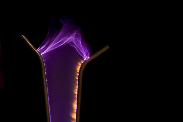
Using this setup I was able to capture some cool high-voltage images and form a functional Jacob's Ladder out of coat hanger wire. Some of these arcs are 2-3" in length:


Eventually, I modified the circuit so that I could use audio to modulate the duty cycle of the signal driving the primary switcher. This created whats called a "Plasma Speaker" – a speaker which emits sound directly from an arc of electricity. This is a project I plan to revisit and re-create into a more polished form-factor. I have some ideas about building a nice 2-way speaker with a glass or ceramic parabolic enclosure.
I lost most of my notes from the project (including the schematic), but I have a video of the speaker in operation embedded blow. Sorry for the potato-quality of this video. I originally uploaded this video to Youtube years ago and it was removed for Copyright infringement. I had lost the original copy of the video and was lucky I could dump the file at all and didn't lose it entirely: