Loop Antenna - Initializing the TMC2130
Now that I can read and write across the SPI interface I am going to write an initialization routine for the TMC2130.
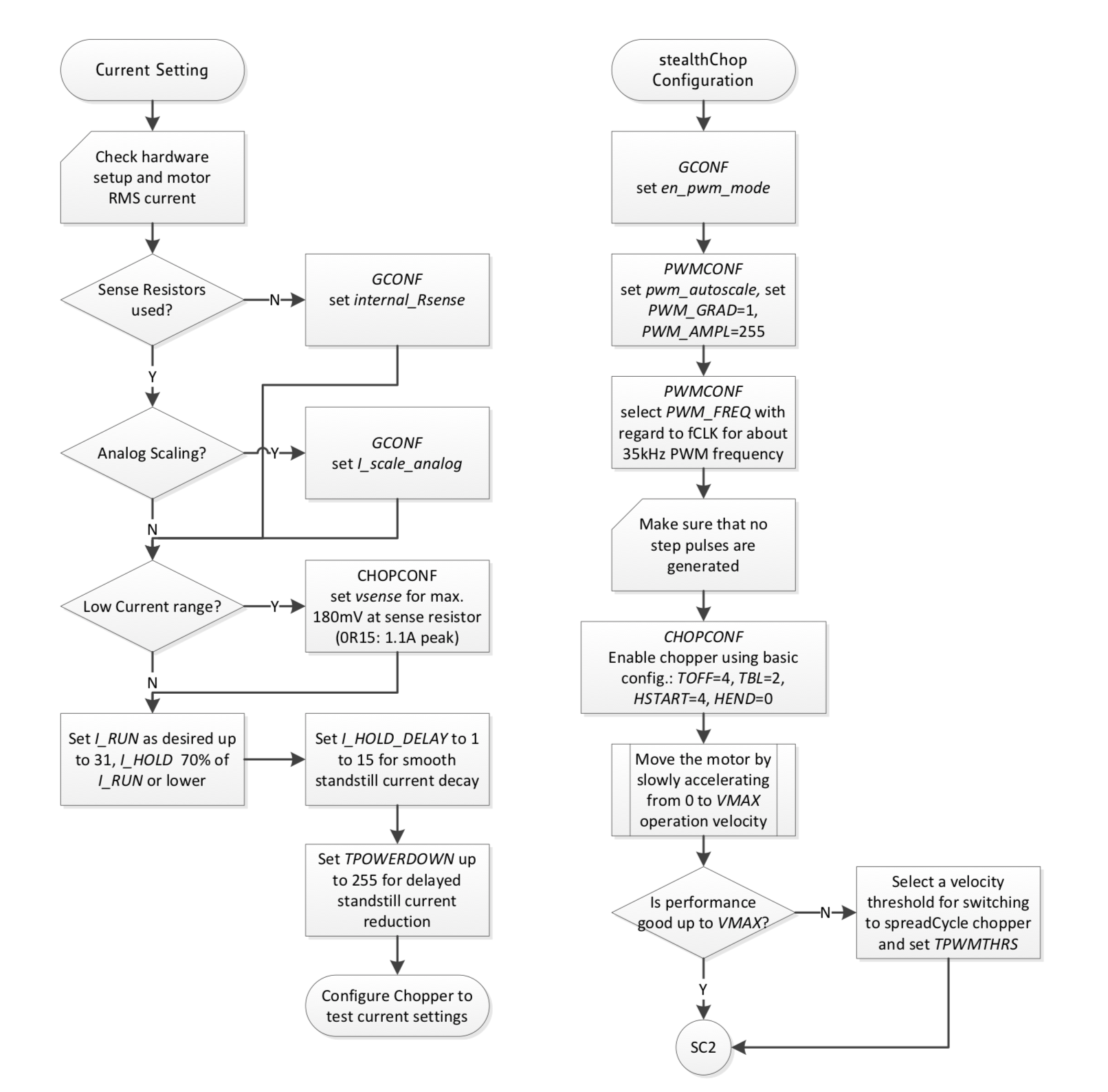
Fig 22.1 and 22.2 in the TMC2130 datasheet show a "quickstart" routine for the TMC2130. First, here is 22.1:

At "SC2" I should be able to move the motor by sending step and direction signals.
I am using an excel spreadsheet to determine the configuration words for each register:

I put the initialization script into main.c and added in the motor step code again. After rebuilding and launching the debugger the motor did not move at all. I eventually narrowed it down to three issues:
- The motor movement was prevented due to thermal shutdowns. I adjusted the run current down to '7' and the hold current to '3' and had no further issues. Eventually I will want to choose these values more carefully.
- The SPI interface on the stm32f401 leaves the clock line at logic-low until the first transfer is initiated regardless of the clock polarity setting. This caused issues on the first command sent to the TMC2130 after a stm32 reset. In order to resolve this I send two dummy bytes of data through the SPI interface without clearing the TMC2130 chip select line. The TMC2130 ignores them since the CS line is high and the SPI clock is setup properly. This happens at the beginning of the TMC2130 initialization function.
- The TMC2130 can be reset by temporarily pulling the VIO input low. When coming out of reset the TMC2130 resets the SPI interface and clears most of the configuration registers. The supply current for VIO is very low (30uA), so it can be driven directly from one of the push-pull outputs of the stm32. I assigned GPIO PB8 to be labeled "TMC_PWR" in STM32CubeMX and then re-generated code. I then set this pin to power cycle the TMC2130 at the start of initialization. I had much more deterministic results after this change.
Here is the final initialization script for now. I will add to this later to tune the motor motion and set the correct thresholds for stall detection. For now, I'd like to write some of the motor control code so I can experiment with various motor parameters with the motor mounted into the system.
    void tmc_init(void) {

        uint8_t rx_data[2] = {0,0};
        uint8_t tx_data[2] = {0,0};

        HAL_GPIO_WritePin(MOTOR_CS_GPIO_Port, MOTOR_CS_Pin, GPIO_PIN_SET);
        HAL_Delay(1);

        //Power cycle the TMC2130
        HAL_GPIO_WritePin(TMC_PWR_GPIO_Port, TMC_PWR_Pin, GPIO_PIN_RESET);
        HAL_Delay(100);
        HAL_GPIO_WritePin(TMC_PWR_GPIO_Port, TMC_PWR_Pin, GPIO_PIN_SET);
        HAL_Delay(100);

        //write 16 bits out of SPI interface to set sck polarity correct.
        while(HAL_SPI_GetState(&hspi1) != HAL_SPI_STATE_READY);
        HAL_SPI_TransmitReceive(&hspi1, (uint8_t *) tx_data,
                (uint8_t *) rx_data,  sizeof(rx_data), HAL_MAX_DELAY );

        //clear the status register by reading it
        tmc_readwrite_register(TMC_REG_GSTAT, 0, 0);

        //TOFF=4, TBL=2, HSTRT=4. HEND=0
        tmc_readwrite_register(TMC_REG_CHOPCONF, 0x10044, 1);

        //IHOLD_IRUN: IHOLD=10, IRUN=31 (max. current), IHOLDDELAY=6
        tmc_set_motor_current(3, 7, 10);

        //approx 1 second to fully power down the motor after motion stops
        tmc_readwrite_register(TMC_REG_TPOWERDOWN, 0x40, 1);

        //en_pwm_mode = 1, DIAG1 set to indicate stall, push-pull active high
        tmc_readwrite_register(TMC_REG_GCONF, 0x2104, 1);

        //switching velocity = 35000
        tmc_readwrite_register(TMC_REG_TPWMTHRS, 0x1F4, 1);

        //approx pwm_autoscale = 1, PWM_GRAD = 1, PWM_AMPL=255
        tmc_readwrite_register(TMC_REG_PWM_CONF, 0x401C8, 1);

        return;
    }
Motor Control Approach
I've thought about a few methods to control the motor. I think the following approach will work well:
- Use a hardware PWM driver on the chip to generate steps in the background.
- Use a motor control task to periodically update the period of the PWM signal to manage velocity and acceleration.
- Configure a timer as a counter to keep track of the total number of steps and provide an interrupt when the total number of steps is reached.
I like this approach because it will run in the background and leave the CPU available for IO, SWR measurements, and other tasks. Using the timer to track distance (total number of steps) makes it simple to poll the current progress and set the velocity according to an acceleration profile. Using the PWM driver to generate steps is also a very accurate way to set motor velocity.
First, I am going to configure TIM1 as a counter. Most of the timers on the STM32 will work – I am using TIM1 specifically because it is a 32-bit timer. Using a 16-bit timer would limit single moves to 65536 steps at 1-step resolution and I know some movements will require more than that. This is how I configured the timer:
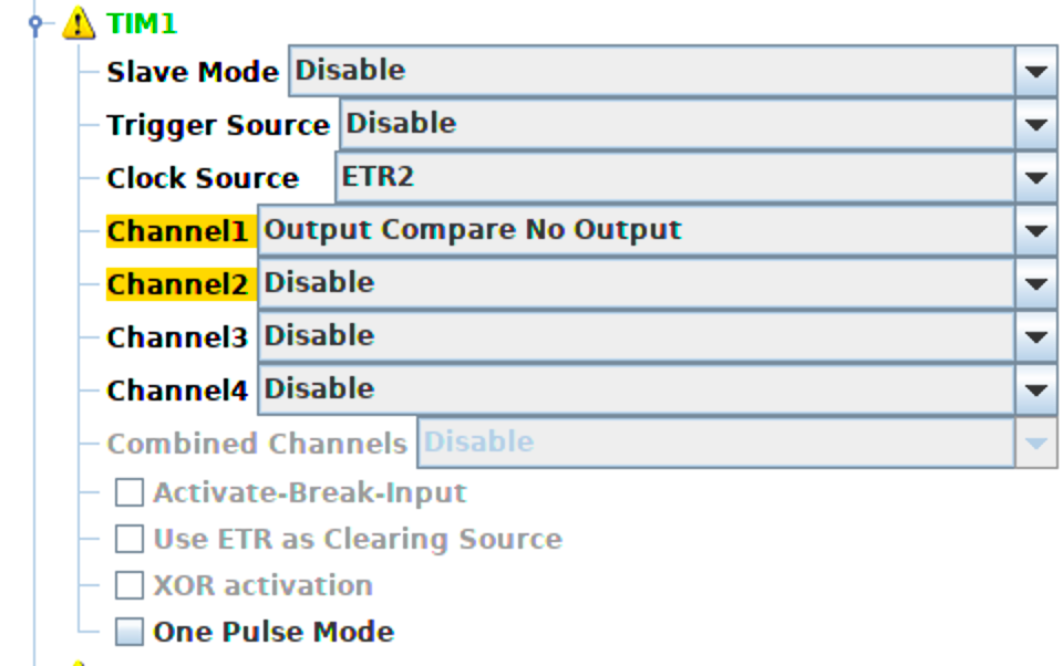
On the STM32F401, the external trigger pin for Timer1, Channel1 is PA12.
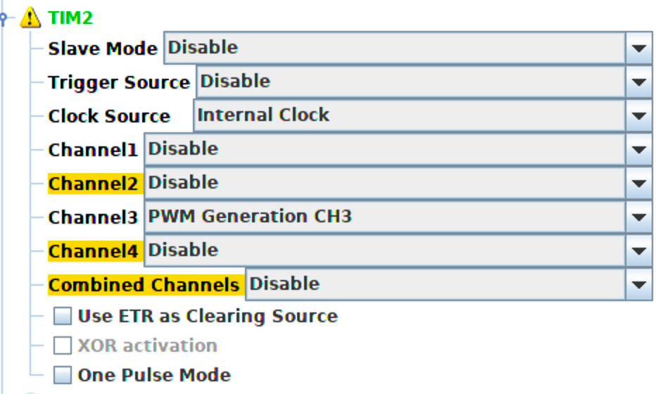
I configured TIM2 (also 32-bit) as the PWM signal driver:
Three registers can be used to setup a movement:
TIM1->AUTORELOAD: Number of steps to take.
TIM2->AUTORELOAD: Period of the PWM signal.
TIM2->COMPARE: Width of the step pulse.
I modified the send_motor_steps() function to setup these registers, start the timers, and enable the interrupt for TIM1.
    void send_motor_steps(uint32_t step_count, uint32_t delay_in_us) {

        __HAL_TIM_SET_AUTORELOAD(&htim1, step_count);
        __HAL_TIM_ENABLE_IT(&htim1, TIM_IT_UPDATE);
        HAL_TIM_OC_Start_IT(&htim1, TIM_CHANNEL_1);

        __HAL_TIM_SET_AUTORELOAD(&htim2,delay_in_us);
        __HAL_TIM_SET_COMPARE(&htim2, TIM_CHANNEL_3, 100);
        HAL_TIM_PWM_Start(&htim2, TIM_CHANNEL_3);

    }
Then I setup the ISR for timer1 (configured in STM32CubeMx) to turn off the timers and end the movement:
    void TIM1_UP_TIM10_IRQHandler(void)
    {
        /* USER CODE BEGIN TIM1_UP_TIM10_IRQn 0 */
        HAL_TIM_PWM_Stop(&htim2, TIM_CHANNEL_3);
        /* USER CODE END TIM1_UP_TIM10_IRQn 0 */
        HAL_TIM_IRQHandler(&htim1);
        /* USER CODE BEGIN TIM1_UP_TIM10_IRQn 1 */
        HAL_TIM_OC_Stop_IT(&htim1, TIM_CHANNEL_1);
        /* USER CODE END TIM1_UP_TIM10_IRQn 1 */
    }
Finally, I put the following code snippet into main.c after the initialization functions:
    uint32_t wait = 40000;
    uint32_t steps = 4000;
    uint8_t move = 1;

    while(1==1) {
        if(move == 1) {
            send_motor_steps(steps,wait);
            move = 0;
        }

    }
The first time the program runs the motor moves 4000 steps and then stops. If I pause operation and use the debugger to set the 'move' variable back to 1 then the motor moves again. If I change the 'wait' to a different value the velocity of the motor movement changes. This is working as intended.
As a next step, I will setup a FreeRTOS task for motor control, create a motor control message queue, and implement acceleration planning for the motor movements.