Robotic Arm - Part 2 - Assembly
In part 1, I shared some of my notes about the BOM for the Moveo robotic arm. In this article I'll share some pictures of the assembly.
All of the plastic parts on the Moveo are 3d-printable. I experimented with and without support material and found the parts printed generally fine without it. My printer at the time wasn't well tuned and didn't have adequate nozzle cooling. With a more modern 3d-printer I think the prints would turn out better with less cleanup required.


Here is an example of a part directly from the printer that was printed without support material:


The turntable on the base of the printer is nicely designed. Getting some of the bushings and nylon washers to press into place took significant effort, but that only needs to be done once. I also had to clean up some of the holes on the side so that the bearings could rotate freely.


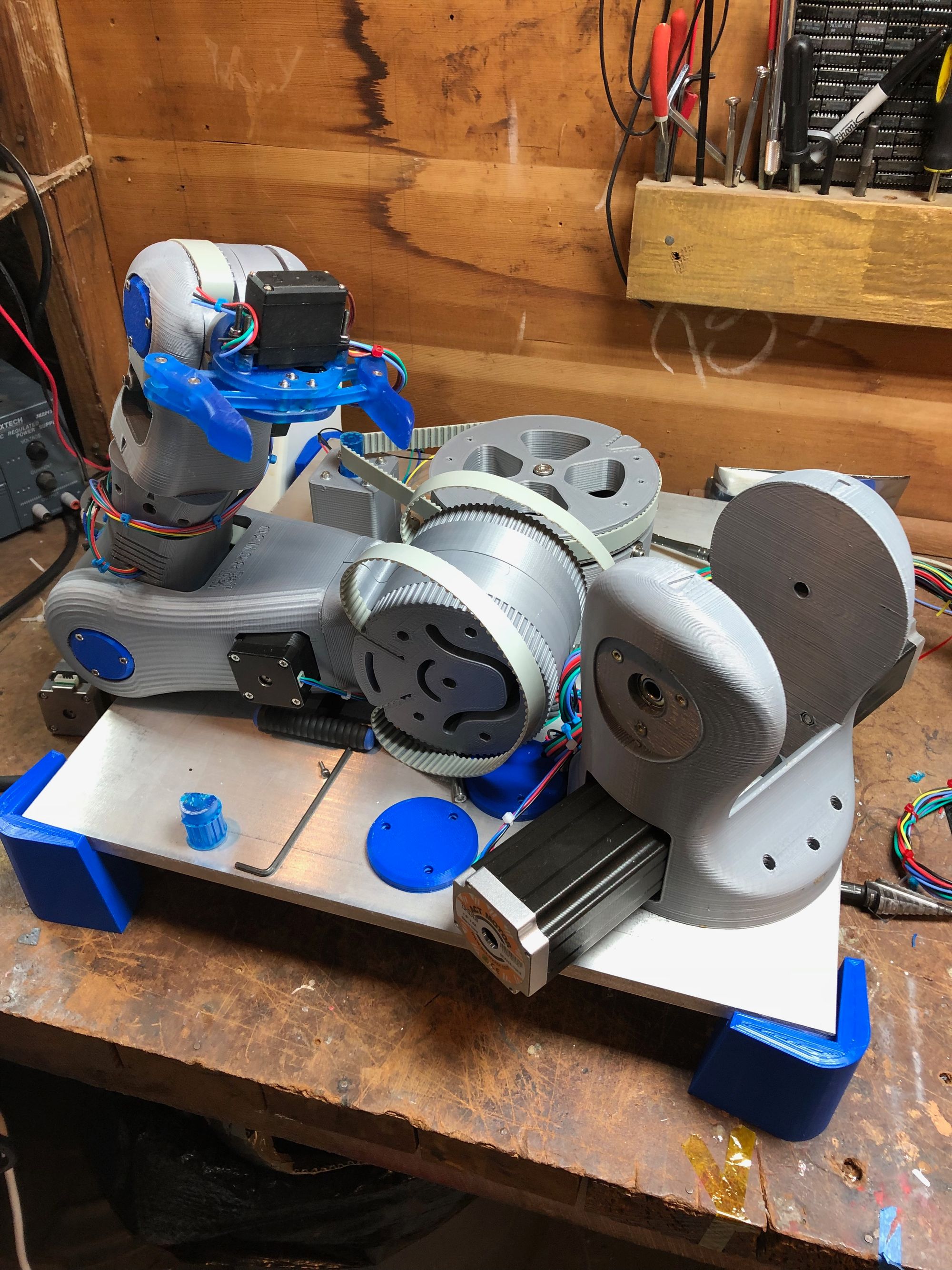
The second joint also went together without issue. I show the 3d-printed pulleys in this image, I ended up replacing them with metal pulleys as they failed on the first use.


Once the first joint is together, most of the otherts are similar enough that the assembly goes easily.


This internal joint is one of the weakest parts of the design. When arm is holding something and the wrist is rotated, this joint requires some significant holding torque. In a later article I will show how to replace this with a 5:1 geared stepper motor to trade off speed for torque.

Once the arm is assembled, you are ready for the fun task of wiring up 7 motors and wiring them to stepper drivers and a controller. :)
